Today I modelled the mouse wheel, there weren’t any problems
getting the shape; I just used an extrude with fillets. However I can’t find
the right tool to get the proper indents on the mouse. I may just have to use
an extrude cut, with a circular pattern. i havent managed to get the right indents in the wheel. ill post a picture when ive finished.
Friday, 11 May 2012

The start to the mouse assignment was very irritating;
firstly I bought the non-compact version of the mouse, which I hadn’t realised
until I had modelled the circuit board and the mouse wheel. Secondly when I did
start modelling the right mouse, I forgot my computer mouse so after I had
pulled apart the mouse I had to use it while modelling it this made the
modelling process very long and tedious. However I did manage to get the
circuit board done without any problems, and the laser reflector took some time
to get right, but they both look good.
the finished products:


the finished products:


Thursday, 5 April 2012
Pump Action Bottle
Modeling the pump action bottle was quite interesting, as I got to learn
how this mechanism works. Unfortunately i couldn’t pull it all apart as it had
been stuck together. Using a torch with Dan, and Phil we figured out how it
works.


Modeling the bottle was fairly simple as it was a basic shape; however modeling
the pump action part was a different story. The revolves weren’t working; I quickly
figured the problems out using the check sketch tool which directed me to the
problem (the sketches were unclosed, and there were a few overhanging lines)
after fixing all these problems the revolve worked perfectly. I also had
another problem, I forgot to half the dimensions as I was doing a revolve; this
cause the pump action part not to fit in the hole of the bottle. After using
the vernier calipers and getting all the dimensions I managed to fix the part
The Part:
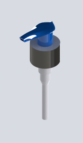
Another part which I had major problems with was the cap of the bottle. The
lofts weren’t working with the lines. I could get half the cap to loft but
after I selected the third guide curve the loft would disappear. After many
attempts on trying to fix the part I gave up. After youtubing many videos I found
out that the boundary boss/bass tool has a lot less constraints and has the
same features of the loft tool. IT WORKED! After getting the lid to loft
properly the next step was to do the engineering drawings.
Final Product

The engineering drawings were a simple task, however I wasn’t sure on what the
deliverables were, so I did 5 drawings
1)
The pump action part
2)
The bottle (by itself)
3)
Exploded View of the pump action part
a.
With a BOM and assembly instructions
4)
An Exploded view of the pump action bottle
a.
With a BOM and assembly instructions
5)
The bottle with all the parts (no exploded view)
Customised Non-Cylindrical Bottle
The customised version of the non-cylindrical bottle was fun to model,
however I came across some problems while modeling; I changed the splines so
that the bottle would have a new interesting look. While adding these new
splines in, I didn’t realise that the splines changed the diameter of the lid. This
was a problem as I had to start remodeling the bottle. Once I had fixed this
problem, the bottle was quite quick to put into the assembly and render.
The finished product:

Non-Cylindrical Bottle
The non-cylindrical bottle was a tougher exercise as I haven’t use the
spline before. Getting the shape of the bottle was difficult, I came across
many issues as I had placed too many points in the spline and the loft wasn’t working;
I had to edit both of the sketches and re-draw the splines which fixed the
problem. After I had modeled the bottle, I had used the cut tool to get the lid
separate from the body. Modeling the lid was difficult as there were many
parts; overall the lid was the hardest and the longest part to model.
Once I had inserted the part into an assembly and started modeling the pop
out lid. Solidworks decided to work against me and it had rolled back the part
due to some coincident joins. However with the help of Dan, I managed to get
the document back to the original save. I’m still yet to model the lid of the
bottle with the top open, and closed.
Mating the bottle was a difficult exercise as I couldn’t mate any of the
parts together. With Dan’s help he taught me that planes from the part could be
mated, which worked out perfectly and the part was mated in no time. Once I had
all the parts of the bottle in the assembly (the main bottle, open lid, and
closed lid) I added the configurations into the assembly which I hadn’t done
before, however once I learned how to do it. They are quite easy.
The final result:

Monday, 26 March 2012
Cylindrical bottle
The Cylindrical bottle was a great re-introduction into Solid works after the break. the time i was modelling the bottle i couldnt get the lines to snap into the right position. it was due to the fact that I hand set enough centerlines and that I didn't notice the small 1mm kinks in the bottle neck. After creating a new sketch with all the right guidelines in i managed to get the neck of the bottle in the right position. however During this modelling process I came across some difficulties such as; getting the radius’s right on the neck of the bottle, and offset entities, when making the thickness of the bottle. I also found some problems when I was doing the revolve. I used the check sketch tool to resolve the problems which stopped me creating the revolve on the bottle.
the finished product:

the finished product:

Subscribe to:
Posts (Atom)