Thursday, 28 June 2012


The animation took over 17 hours to render. I used 25 fps with a maximum resolution. I made the camera follow a spline around the front of the mouse, while it explodes then the model combines again at the end. the Animation rendering stopped unexpectedly 3 times. so i had to restart it  from the ending point. luckily the files didn't corrupt when this happened. i managed to change the codec of the file so it would insert to windows movie maker; which I used to merge the files and compress it. 

Final Animation:

Mouse Assignment 3


-           
I started off this project by drawing the shape of the mouse that i wanted; i sketched out the side view, including the roller wheel, followed the bottom view then a bottom view of the mouse button cover. The mouse is designed to be sleek and organic. This mouse has 3 parts; a lower, middle and upper housing; with the same 3 components that were used in the previous task.

Profile Images: 

Mouse Side View

Mouse Button Cover

Mouse Bottom View
I used the same process for the lower as the previous task for modelling this mouse.  I inserted the sketch pictures into Solid Works and used centre lines to set the correct size of the mouse. I used the spline tool and traced one side of the sketch then mirrored it to ensure symmetry.  I then traced the side spline which i will project to make the top profile for the loft. When i tried to project this curve it didn’t complete. So i had to make a different profile which i would use for project curve; one that stopped shorter so i could make line up with the picture.

Lower Housing Surface:
Completed Lower Housing
I did the middle and upper step using a surface fill; with constraint curves I used the spline tool to create height and the shape of the part. I then used to profiles to control the width.  I then used the filled surface tool which made the shape. At first I had a few problems creating this surface fill. However I managed to fix as the lower housing spline finished as a point, not a curve; changing this fixed it.
I then made a spline on the side view which i extruded both ways so i could trim the upper part of this housing off to make a better fit for the mouse button cover.

Split profile for middle housing and mouse button cover

Finished Middle Housing

I then made two another spline on the side view, and another front view which I used to create another filled surface, this created the mouse button cover.
Mouse Button Cover

Finished Mouse Body
After i had finished creating the mouse body i split all bodies and inserted them into new parts. I then inserted the parts into an assembly including the circuit board, mouse wheel and reflector. Once all the parts were in the assembly, I then starting adding all the inside supports and connections i did most of this inside the assembly however every time i changed a part the model in the assembly turned yellow. I added in a few connections on each part to make the part work. Some of the interior parts were based off the old model but the style was changed in order to fit the design. Overall the model was a lot easier to model this time around as i knew what problems to look out for.

Finished Rendered Model: 


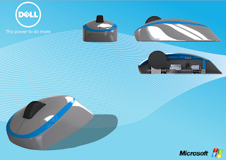
Rendering this time around was a lot better; i used a higher resolution and better studio lighting. This gave a nicer image and better reflections. I did 8 overall renders showing the different views and sections of the mouse. The presentation board looks a lot better this time; i used a combination of Adobe Photoshop and Illustrator for the background, and just made a simple presentation page showing the views of the mouse with a section view.

Finished Photo board: 


Sunday, 27 May 2012


So the past few days have been very eventful in the world of CADD. With all the errors that were happening with the split part, Dan managed to save my model and I didn’t have to start again which was a huge relief. After I managed to split all the parts I inserted the model into an assembly, which snapped together due to the master part; and i inserted all the bits into the model (the Scroll wheel, Reflector and the circuit board (and they all fit nicely).


Getting all the extrudes on the bottom housing and the mouse button cover were simple thanks to the assembly, however they were very tedious to get them to all fit nicely. However i did have a problem; the shell feature wasn’t working on the middle housing due to a minimal radius, or something. I tried every way I know how to solve it, and most of them didn’t look that pretty so I ended up having to shell it at 0.010mm and thicken it to 1mm which worked after playing around with the part for two hours or so. The process of doing all the bits in the middle housing part took quite a long time to get right but once I finished it, it seemed to fit together pretty well.


The last thing i modelled was the USB cable, which was quite easy just a few splines, with a surface sweep and extrudes and just sat it on the exterior of the mouse. I couldn’t find the toolbox on my computer i don’t think solid works installed completely on here; which was annoying as i would have liked to get the right screw in the back seeing it lined up pretty much perfectly.


Finally was the rendering and the advert they took some time to get right. I chose pretty simple colours and camera angles. I changed the lights in solid works to just one major spot light just to see how the renderings will turn out with it; and my advert was pretty simple, i didn’t want to do anything to wild seeing that’s how Microsoft does its advertisements.

Edit: I Changed the Setting as the one light didnt seem to work, insted I just used a studio room with fill lights.


Final Rendering / Product:


Advert:

Thursday, 24 May 2012

So today i started splitting the mouse i drew a spline that matches the profile of the mouse button cover, i then extruded the surface profile.

I then offset the surface of the mouse button surface inward by 2mm and trimmed the offset surface, using a sketch which is roughly about 1.5mm inward from the cover.

Thirdly I filled the extruded surface and the offset mouse button cover which created the surface that ill split the mouse with.

I went to fill the middle housing with the fill surface tool, however due to the surfaces being knitted incorrectly it wouldn’t work. Thanks to Dan, we managed to get that fixed. And by we i meant him!

I then went to split the middle housing from the mouse button cover, however when i try to split the part it creates some massive crater in the middle housing part. or if i change the settings on the split part the edges will become all messed up. So i’m deciding if i don’t managed to get this problem fixed on Friday at the last tute session i will have to restart the mouse body again. Which will be a pain, but it might just be easier.

The top button mouse cover was an easy surface to create; I used a constraint curve to make sure the shape was equal and not flat. I used the surface fill tool and the blue line shown before as the boundary, and the constraint curve to ensure that it was equal throughout the entire surface. I then cut the curve in half using the plane i sketched the constraint curve on.

I then had to model the finger troughs, I made an inverted curve which i mirrored to make the troughs even and then surface filled the surface again. The last step for modelling was the trough where the mouse roller goes. I made a plane on top of the mouse, and while looking at the top view of the picture i traced one half of the trough where the mouse wheel goes and mirrored it, for equal curvature, i then trimmed the surface creating a hole in the mouse. Finally made another inverted constraint curve for the convex surface; which i then surface filled with the constraint curve which finished the surface of the mouse.

finished mouse:

Monday, 21 May 2012


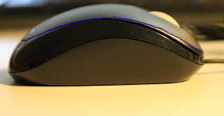
The middle part of the mouse was fairly simple to model, firstly I made a sketch of the side profile of the mouse shown here in blue (sorry about the wonky line, i did it with my trackpad).


This profile was then mirrored around so that it made the shape of the top part. I then use a projected curve using the profile from the bottom part and the profile which was shown in blue. I then had to use guide curves to create the proper shape. And  finally i used the surface loft tool to create the middle part of the mouse (highlighted).

I started modelling the mouse today, the bottom of the mouse was fine to get. I made the bottom of the mouse using the spline tool, then mirroring it to ensure the shape of my mouse was symmetrical. I then used the side view picture supplied by Dan to create guide curves, to create the surface loft; (but we will get to that later) which i then mirrored again so the shape would be the same on each side. I created 12 guide curves for the bottom half of the mouse ( 1 on the front and the back and 5 on each side).  I used the surface loft tool to create the bottom half of my mouse; then used the planar surface tool to fill in the bottom. I then use the face fillet tool (with continuous curvature) to create the fillet between the side and the bottom at a radius of 2mm.

The complete bottom of the mouse:

Friday, 11 May 2012

Today I modelled the mouse wheel, there weren’t any problems getting the shape; I just used an extrude with fillets. However I can’t find the right tool to get the proper indents on the mouse. I may just have to use an extrude cut, with a circular pattern. i havent managed to get the right indents in the wheel. ill post a picture when ive finished.


The start to the mouse assignment was very irritating; firstly I bought the non-compact version of the mouse, which I hadn’t realised until I had modelled the circuit board and the mouse wheel. Secondly when I did start modelling the right mouse, I forgot my computer mouse so after I had pulled apart the mouse I had to use it while modelling it this made the modelling process very long and tedious. However I did manage to get the circuit board done without any problems, and the laser reflector took some time to get right, but they both look good.

the finished products:


Thursday, 5 April 2012

Pump Action Bottle

Modeling the pump action bottle was quite interesting, as I got to learn how this mechanism works. Unfortunately i couldn’t pull it all apart as it had been stuck together. Using a torch with Dan, and Phil we figured out how it works.

Modeling the bottle was fairly simple as it was a basic shape; however modeling the pump action part was a different story. The revolves weren’t working; I quickly figured the problems out using the check sketch tool which directed me to the problem (the sketches were unclosed, and there were a few overhanging lines) after fixing all these problems the revolve worked perfectly. I also had another problem, I forgot to half the dimensions as I was doing a revolve; this cause the pump action part not to fit in the hole of the bottle. After using the vernier calipers and getting all the dimensions I managed to fix the part

The Part:


Another part which I had major problems with was the cap of the bottle. The lofts weren’t working with the lines. I could get half the cap to loft but after I selected the third guide curve the loft would disappear. After many attempts on trying to fix the part I gave up. After youtubing many videos I found out that the boundary boss/bass tool has a lot less constraints and has the same features of the loft tool. IT WORKED! After getting the lid to loft properly the next step was to do the engineering drawings.

Final Product


The engineering drawings were a simple task, however I wasn’t sure on what the deliverables were, so I did 5 drawings

1)      The pump action part

2)      The bottle (by itself)

3)      Exploded View of the pump action part

a.       With a BOM and assembly instructions

4)      An Exploded view of the pump action bottle

a.       With a BOM and assembly instructions

5)      The bottle with all the parts (no exploded view)

Customised Non-Cylindrical Bottle


The customised version of the non-cylindrical bottle was fun to model, however I came across some problems while modeling; I changed the splines so that the bottle would have a new interesting look. While adding these new splines in, I didn’t realise that the splines changed the diameter of the lid. This was a problem as I had to start remodeling the bottle. Once I had fixed this problem, the bottle was quite quick to put into the assembly and render.

The finished product:


Non-Cylindrical Bottle


The non-cylindrical bottle was a tougher exercise as I haven’t use the spline before. Getting the shape of the bottle was difficult, I came across many issues as I had placed too many points in the spline and the loft wasn’t working; I had to edit both of the sketches and re-draw the splines which fixed the problem. After I had modeled the bottle, I had used the cut tool to get the lid separate from the body. Modeling the lid was difficult as there were many parts; overall the lid was the hardest and the longest part to model.

Once I had inserted the part into an assembly and started modeling the pop out lid. Solidworks decided to work against me and it had rolled back the part due to some coincident joins. However with the help of Dan, I managed to get the document back to the original save. I’m still yet to model the lid of the bottle with the top open, and closed.

Mating the bottle was a difficult exercise as I couldn’t mate any of the parts together. With Dan’s help he taught me that planes from the part could be mated, which worked out perfectly and the part was mated in no time. Once I had all the parts of the bottle in the assembly (the main bottle, open lid, and closed lid) I added the configurations into the assembly which I hadn’t done before, however once I learned how to do it. They are quite easy.


The final result:

Monday, 26 March 2012

Cylindrical bottle

The Cylindrical bottle was a great re-introduction into Solid works after the break. the time i was modelling the bottle i couldnt get the lines to snap into the right position. it was due to the fact that I hand set enough centerlines and that I didn't notice the small 1mm kinks in the bottle neck. After creating a new sketch with all the right guidelines in i managed to get the neck of the bottle in the right position. however During this modelling process I came across some difficulties such as; getting the radius’s right on the neck of the bottle, and offset entities, when making the thickness of the bottle. I also found some problems when I was doing the revolve. I used the check sketch tool to resolve the problems which stopped me creating the revolve on the bottle.

the finished product: